Steam Tank(Internal)Heater Plate Power Breaker Switch Steam Tank Water Level Sensor Over-heating Controller Pressure Switch Boiler Operation Panel Filter Strainer Storage Tank Water Level Sensor of Storage Tank Solenoid Valve of Storage Tank Water Supply Grounding Terminal Water Supply Hole Steam Condensation Collection Opening Water Tank Evaporation Release Opening Filter Strainer Water Feed Pump Check Valve Steam Tank Cleaning Hole Steam Tank Cleaning Valve Operation Power Breaker Power Supply Terminal Block Electrical Attachment Panel Safety Valve Steam Release Valve Steam Release Hole of Safety Valve Zoom In Power Supply Terminal Block Operation Power Breaker Terminal Block Heater Magnetic Contactor Pump Magnetic Contactor Water Level Control Relay of Storage Tank Steam Tank Level Control Relay Alarm Water Level Control Relay Pressure Gauge Power Supply Lamp Heater On Switch Alarm Stop, Recovery Switch Low Water Level Alarm Buzzer Heater Operation Lamp Pump Operation Lamp


Select Boiler Volume.

 
Diagram Number
Parts Name
Parts
Spec.
Materials
Model
Number
Symbol
- 01
Pressure Switch
10§¸/§²
--
PSNS-C110
PS©û
- 02
Steam Release Valve
15A, 20A, 25A
Globe Valve
10Kg
--
- 03
Steam Tank Cleaning Valve
15A, 20A
Gate Valve
10Kg
--
- 04
Steam Release Hole
of Safety Valve
20A, 25A
Cast Iron Elbow
--
--
- 05
Power Supply Terminal Block
--
--
--
--
- 06
Safety Valve
20A, 25A
Bronze
--
--
- 07
Check Valve
15A
Bronze
PT14
--
- 08
Storage Tank
7Lt, 20Lt
SUS
--
--
- 09
Water Level Sensor
of Storage Tank
M18
Teflon
EH-1
--
- 10
Solenoid Valve of Storage Tank
Water Supply
15A
--
DK-2140
SO©û
- 11
Water Feed Pump
0.2~0.75KW
Cast Iron
--
P©û
- 12
Steam Tank Cleaning Hole
--
Cast Iron
Elbow
--
--
- 13
Grounding Terminal
M6
Steel
--
--
- 14
Water Supply Hole
15A
--
15A 10K
--
- 15
Filter Strainer
15A
Cast Iron
10K15A½Å¿ì
--
- 16
Pump Air Vent
--
--
--
--
- 17
Pump Anti-Freeze Water
Release Hole
--
--
--
--
- 18
Boiler Operation Panel
--
--
--
--
- 19
Power Breaker Switch
--
--
--
NFB1
- 20
Heater Plate
--
--
--
--
- 21
Steam Tank (Internal)
--
--
--
--
- 22
Electrical Attachment Panel
--
--
--
--
- 23
Steam Tank Water Level Sensor
M18
Teflon
EH-1
--
- 24
Steam Condensation
Collection Opening
15A, 20A
SUS
--
--
- 25
Water Tank Evaporation
Release Opening
25A
SUS
--
--
- 26
Power Supply Lamp
220V 25¢±
--
YSPL2
L0
- 27
Pressure Gauge
60¢± 10§¸
/§²
--
--
--
- 29
Pump Operation Lamp
220V 25¢±
--
YSPL2
L©û
- 30
Alarm Stop, Recovery Switch
13.5¡¿29
--
DAJEON
LS©ü
- 32
Low Water Level Alarm Buzzer
220V 30¢±
--
YSMB3
BZ
- 33
Heater Operation Lamp
220 25¢±
--
YSPL2
L©ü
- 34
Heater On Switch
13.5¡¿29
--
DAJEON
LS©û
- 37
Over-heating Controller
300¡É
--
--
TC
- 38
Terminal Block
20A 15P
--
YSFT2015
TB
- 39
Heater Magnetic Contactor
--
--
--
MS©û- ©û
- 40
Pump Magnetic Contactor
10A
--
GMC-12
MS©ü
- 41
Operation Power Breaker
--
--
NFB-2
--
- 42
Water Level Control
Relay of Storager Tank
220/10V
--
DSF-88
FR©û
- 43
Steam Tank Level Control Relay
220/10V
--
DSF-88
FR©ü
- 44
Alarm Water Level control Relay
220/10V
--
DSF-88
FR©ý
- 45
Current Transformer
--
--
--
--
- 46
Heater MagneticContactor
--
--
--
MS©û- ©ü
- 48
Alarm Terminal Block
--
--
--
--


¢º 
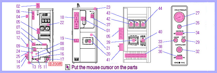
Close all valves, and release the valve installed on the water supply opening (-14).
¢º If the power breaker switch (-19) is flipped up, the power supply lamp (-26) will light up.
  (In the case of 380V or 440V, also raise the operation power breaker (-41).)
¢º If the heater on switch (-29) is pressed, the lamp comes on and the reserve water
  tank (-08) fills up. When it is filled with water, the pump operation lamp (-29) lights up and
  the pump starts to operate. Water begins to be supplied to the steam generation tank.
¢º At this time, there is no water inside the steam generation tank (-21) so that the low water l
  evel alarm buzzer (-32) will sound. The alarm can be stopped by pressing the alarm stop
  switch (-30). The low level alarm will sound when enough water has filled up and the
  alarm recovery switch (-31) is pressed. Even if the alarm is not reset, the low-level
  automatic heater limiter device will sound so that there is no need to worry.
¢º When the boiler is operated for the very first time, open the pump air vent (-16) to
  release air, and close it when a stream of water about 1m high shoots out. If there is no
  water in the storage water tank (-08), the pump will not operate. Repeat the on/off
  operation several times and when the steam generation tank (-21) is sufficiently filled with
  water, the heater operation lamp (-33) will light up and heating will begin.
¢º After a while, the pressure gauge (-27) will begin to move and steam will begin to be
  generated. At this time, slightly open the steam release valve (-25) and when the air
  inside is released, the steam pressure increase will be slightly faster.
¢º When the steam gauge (-25) indicates about 5§¸/§², open the steam release valve
  (-02) and use the steam.
¢º is withdrawal of the condensed water, steam will come out from the water tank steam
  opening (-25), so discharge outside.